Ariens Platinum 30 Specifications Page 31
- Page / 42
- Table of contents
- TROUBLESHOOTING
- BOOKMARKS
- 921 Series 1
- Sno-Thro 1
- INTRODUCTION 2
- TABLE OF CONTENTS 2
- UNAUTHORIZED REPLACEMENT 3
- DISCLAIMER 3
- DELIVERY 3
- 1. DANGER! 5
- 2. DANGER! 5
- 3. DANGER! 5
- EMISSION CONTROL SYSTEM 6
- ASSEMBLY 8
- PACKAGE CONTENTS 8
- (921023) 10
- Install Discharge Chute and 11
- 030, 032, 035) 11
- Remote Deflector Control 13
- CONTROLS AND FEATURES 15
- OPERATION 17
- FILLING FUEL TANK 20
- GASOLINE 20
- STARTING AND SHUT OFF 22
- Manual Start 22
- Electric Start (120V) 22
- Shut Off 23
- SNOW REMOVAL 23
- Tips for Operation 23
- TRAVELING 23
- TRANSPORT 23
- MAINTENANCE 24
- SCHEDULE 24
- GENERAL LUBRICATION 26
- SERVICE AND ADJUSTMENTS 27
- REMOTE DEFLECTOR 28
- CONTROL ADJUSTMENT 28
- DISCHARGE CHUTE (921028, 029) 28
- DISCHARGE CHUTE CONTROL 28
- (921023, 024, 030, 032, 035) 28
- SPEED SELECTOR ADJUSTMENT 29
- ATTACHMENT CLUTCH/BRAKE 29
- ADJUSTMENT 29
- Remove Attachment Cable Slack 29
- Clearance 30
- Check Attachment Brake 30
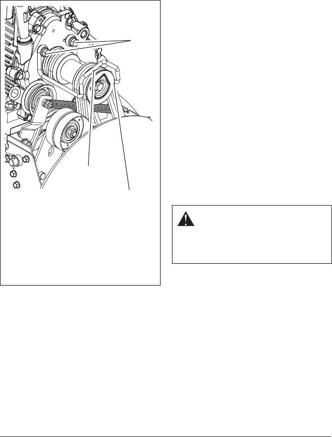
- TRACTION DRIVE CLUTCH 31
- TRACTION DRIVE BELT 32
- REPLACEMENT 32
- 921023, 024, 030, 032, 035 32
- 921028, 029 32
- FRICTION DISC REPLACEMENT 33
- TRACK TENSION ADJUSTMENT 34
- HEIGHT ADJUSTER CABLE 34
- ADJUSTMENT (921023) 34
- SERVICE PARTS 35
- ACCESSORIES 35
- TROUBLESHOOTING 36
- SPECIFICATIONS 37
- , Sno-Tek 39
- Chore Performing Equipment 39
- Limited Warranty 39
- Exceptions and Limitations 40
- Customer Responsibilities 40
- Sno-Chore_2012_Rev. A 41
- 655 West Ryan Street 42
- Brillion, WI 54110 42
- 920-756-4688 42
Related products and manuals for Garden tools Ariens Platinum 30
 (44 pages)
(2 pages)
(44 pages)
(2 pages)
 (42 pages)
 (42 pages)
(8 pages)
(41 pages)
(32 pages)
(42 pages)
(8 pages)
(41 pages)
(32 pages)
© 2020, manymanuals.com. All rights reserved. | 4.470 s |
 Manymanuals.com
 Manymanuals.de
 Manymanuals.fr
 Manymanuals.it
 Manymanuals.pl
 Manymanuals.cz
 Manymanuals.es
 Manymanuals-pt.com
Comments to this Manuals