Ariens 946150 ST622 CARB User Manual Page 13
- Page / 21
- Table of contents
- TROUBLESHOOTING
- BOOKMARKS
- String Trimmer 1
- TABLE OF CONTENTS 2
- INTRODUCTION 2
- 1. DANGER! TO AVOID SERIOUS 4
- INJURY OR DEATH 4
- ASSEMBLY 7
- CONTROLS AND FEATURES 8
- OPERATION 9
- Pre-Start 10
- Starting the Engine 10
- Stopping the Engine 10
- MAINTENANCE 11
- Maintenance Schedule 11
- SERVICE AND ADJUSTMENTS 12
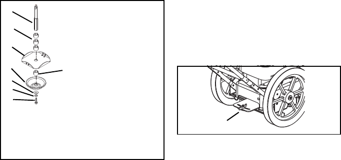
- SWIVEL HEAD ADJUSTMENT 13
- CUTTING HEIGHT ADJUSTMENT 13
- HEIGHT GUIDE REPLACEMENT 13
- CONTROL BAIL TRAVEL 14
- ADJUSTMENT 14
- DRIVE BELT REPLACEMENT 14
- TROUBLESHOOTING 16
- SERVICE PARTS 17
- SPECIFICATIONS 17
- Ariens Limited 18
- Warranties 18
- LIMITATION OF REMEDY AND 19
- DISCLAIMER OF FURTHER 19
- WARRANTY 19
- ALW2-62905 20
© 2020, manymanuals.com. All rights reserved. | 1.726 s |
 Manymanuals.com
 Manymanuals.de
 Manymanuals.fr
 Manymanuals.it
 Manymanuals.pl
 Manymanuals.cz
 Manymanuals.es
 Manymanuals-pt.com
Comments to this Manuals