Ariens Snow Blower 920006 User Manual Page 1
Browse online or download User Manual for Snow throwers Ariens Snow Blower 920006. Ariens Snow Blower 920006 User's Manual
- Page / 34
- Table of contents
- TROUBLESHOOTING
- BOOKMARKS
- Sno-Thro® 1
- TABLE OF CONTENTS 2
- INTRODUCTION 2
- PRODUCT REGISTRATION 3
- UNAUTHORIZED REPLACEMENT 3
- DISCLAIMER 3
- DELIVERY 3
- 08000127A 4
- SAFETY RULES 5
- ASSEMBLY 8
- (Figure 6) 9
- Interlock 9
- CONTROLS AND FEATURES 11
- OPERATION 12
- FILLING FUEL TANK 15
- GASOLINE 15
- PRE-START 16
- TO STOP IN AN EMERGENCY 16
- STARTING AND SHUT OFF 16
- TRAVELING 17
- TRANSPORT 17
- SNOW REMOVAL 17
- MAINTENANCE 18
- MAINTENANCE SCHEDULE 18
- Auger Shaft 19
- SERVICE AND ADJUSTMENTS 20
- SHEAR BOLTS 21
- DISCHARGE CHUTE DEFLECTOR 21
- DISCHARGE CHUTE 21
- SPEED SELECTOR 22
- ADJUSTMENT 22
- ATTACHMENT DRIVE BELT 22
- REPLACEMENT 22
- Replace Attachment Drive Belt 23
- TRACTION DRIVE BELT 24
- ATTACHMENT CLUTCH/BRAKE 24
- Clearance 25
- Spring Extension 26
- TRACTION DRIVE CLUTCH 27
- FRICTION DISC REPLACEMENT 28
- SERVICE PARTS 29
- ACCESSORIES 29
- TROUBLESHOOTING 30
- SPECIFICATIONS 31
- Three-Year Limited Sno-Thro 32
- Warranty 32
- Limitations 33
- Disclaimer 33
- Ariens Company 34
- 655 West Ryan Street 34
- Brillion, WI 54110-1072 34
- 920-756-2141 34
Summary of Contents
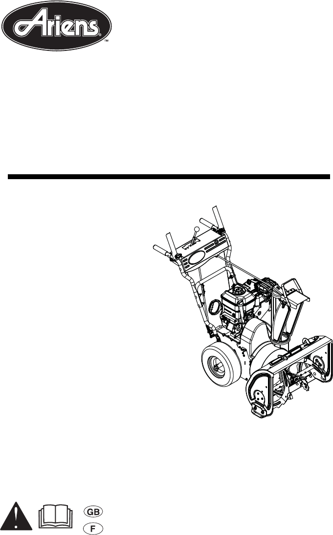
Owner/Operator ManualManuel Du Propriétaire/UtilisateurModels920006 – Compact 24920007 – Compact 20920010 – Compact 24Sno-Thro®03882500B 9/09Printed i
GB - 10Check Tire PressureCheck tire pressure and adjust to the pressure listed on tire sidewall.Check Auger Gearcase OilCheck oil level in auger gear
GB - 111. Attachment Clutch Lever2. Speed Selector3. Traction Drive Clutch Lever4. Chute Crank 5. Muffler Guard6. Discharge Chute Deflector7. Discharg
GB - 12CONTROLS AND FEATURESSee Figure 7 for all Controls and Features locations.Dual Handle Interlock When Attachment Clutch and then Traction Drive
GB - 13Speed SelectorPosition the Speed Selector in the appropriate speed notch to control forward and reverse travel.Forward:(6) Fastest(1) SlowestRe
GB - 14Recoil Starter Handle When pulled, handle will turn engine over.IMPORTANT: DO NOT let handle snap back against starter.See Starting and Shut O
GB - 15Scraper BladeThe scraper blade allows the back of the housing to keep better contact with the surface being cleared. It also prevents damage to
GB - 165. Fill fuel tank to within 1/2 in. (1.2 cm) below bottom of filler neck with unleaded gasoline. 6. Replace Fuel Cap and tighten.7. ALWAYS clea
GB - 179. Repeat steps 7 and 8 until engine starts. (If engine does not start, refer to TROUBLESHOOTING on page 30.)10. Adjust choke as needed.11. Set
GB - 18Ariens Dealers will provide any service or adjustments which may be required to keep your unit operating at peak efficiency. Should engine serv
GB - 19CHECK CLUTCH OPERATIONAuger / impeller must stop within 5 seconds when attachment clutch/impeller brake lever is released.Wheels must stop quic
GB - 2SAFETY . . . . . . . . . . . . . . . . . . . . . . . . . 4ASSEMBLY. . . . . . . . . . . . . . . . . . . . . . . 8CONTROLS and FEATURES. . . .
GB - 20SCRAPER BLADEIMPORTANT: Damage to auger/impeller housing will result if blade wears down too far.Scraper blade is adjustable to compensate for
GB - 21SHEAR BOLTSIMPORTANT: Use only Ariens shear bolts for replacement. Use of any other type of shear bolt may result in severe damage to unit and
GB - 22SPEED SELECTOR ADJUSTMENTTo adjust (Figure 18):1. Disconnect adjustment pivot pin from speed selector arm. Save hardware for reinstallation.2.
GB - 237. Remove hex bolts securing housing to frame (two on each side). Tip housing and frame apart on pivot pin.8. Remove attachment drive belt from
GB - 24TRACTION DRIVE BELT REPLACEMENTNOTE: Housing and frame must be tipped apart and attachment drive belt removed from engine sheave in order to ch
GB - 252. Loosen jam nut on cable adjustment barrel, and then turn the adjustment barrel down to shorten cable and remove all cable slack. See Figure
GB - 26Adjust the Attachment Clutch Cable Spring Extension1. Check the attachment clutch cable spring extension. Measure the length of the attachment
GB - 27Check Belt Finger Clearance (Figure 29)1. With clutch lever engaged, the belt finger located opposite the belt idler must be less than 1/8 in.
GB - 28FRICTION DISC REPLACEMENTRemove Friction Disc (Figure 31 and Figure 32):1. Shut off engine, remove key, disconnect spark plug wire and allow un
GB - 29SHORT TERMIMPORTANT: NEVER spray unit with high pressure water or store unit outdoors.Run with attachment clutch engaged a few minutes after ea
GB - 3• Record Unit Model and Serial numbers here.• Record Engine Model and Serial numbers here.PRODUCT REGISTRATIONThe Ariens dealer must register th
GB - 30TROUBLESHOOTINGPROBLEM PROBABLE CAUSE CORRECTION Engine will not crank/start.1. Fuel tank is empty.2. Fuel shut-off valve closed.3. Build up of
GB - 31SPECIFICATIONSModel Number 920006 920007 920010Description Compact 24 Compact 20 Compact 24Engine Briggs & Stratton900 SeriesBriggs &
ARIENS COMPANYGRAVELY® | STENS® | LOCKE® | NATIONAL® MOWER | BYNORM® | EVERRIDE® | GREAT DANE® Snow_200832Three-Year Limited Sno-Thro® WarrantyAriens
ARIENS COMPANYGRAVELY® | STENS® | LOCKE® | NATIONAL® | BYNORM® | EVERRIDE® | GREAT DANE® Snow_200833Limitations• Batteries are warranted only for a p
Ariens Company655 West Ryan StreetBrillion, WI 54110-1072920-756-2141www.ariens.com
GB - 4SAFETY ALERTSLook for these symbols to point out important safety precautions. They mean:Attention! Personal Safety Is Involved!Become Alert!
GB - 51. WARNING!2. DANGER! 3. DANGER!SAFETY RULESRead, understand, and follow all safety practices in Owner/Operator Manual before beginning assembly
GB - 6DO NOT operate near drop-offs, ditches, or embankments. Unit can suddenly turn over if a wheel is over the edge of a cliff or ditch, or if an ed
GB - 7Never leave a running unit unattended. ALWAYS shut off engine before leaving unit. ALWAYS remove key to prevent unauthorized use.Never carry pas
GB - 8PACKAGE CONTENTSASSEMBLYTools Required:• Pliers• Open-End Wrenches: 3/8, 7/16, 1/2, 9/16 in. and/or Adjustable Wrench•Tire GaugeUnfold Handlebar
GB - 9Install Discharge Chute (Figure 5)1. Grease underside of discharge chute ring (if not already greased).2. Remove mounting hardware from the bott
Related products and manuals for Snow throwers Ariens Snow Blower 920006
 (36 pages)
(8 pages)
(34 pages)
(30 pages)
(36 pages)
(8 pages)
(34 pages)
(30 pages)
 (29 pages)
 (33 pages) (44 pages)
 (65 pages)
 (28 pages)
© 2020, manymanuals.com. All rights reserved. | 1.908 s |
 Manymanuals.com
 Manymanuals.de
 Manymanuals.fr
 Manymanuals.it
 Manymanuals.pl
 Manymanuals.cz
 Manymanuals.es
 Manymanuals-pt.com
Comments to this Manuals