Ariens 938018 - SS722EC Specifications
Browse online or download Specifications for Snow throwers Ariens 938018 - SS722EC. Ariens 938018 - SS722EC Specifications [en] User Manual
- Page / 24
- Table of contents
- BOOKMARKS
- Sno-Thro 1
- TABLE OF CONTENTS 2
- INTRODUCTION 2
- PRODUCT REGISTRATION 3
- UNAUTHORIZED REPLACEMENT 3
- DISCLAIMER 3
- DELIVERY 3
- SAFETY ALERTS 4
- NOTATIONS 4
- PRACTICES AND LAWS 4
- REQUIRED OPERATOR 4
- TRAINING 4
- SAFETY DECALS AND 5
- LOCATIONS 5
- SAFETY RULES 6
- ASSEMBLY 8
- Discharge Chute Assembly 9
- Fill Engine Fuel Tank 9
- CONTROLS & FEATURES 10
- OPERATION 11
- FILLING FUEL TANK 12
- PRE-START 12
- STOPPING IN AN EMERGENCY 13
- STARTING AND SHUTTING OFF 13
- SNOW REMOVAL 13
- MAINTENANCE SCHEDULE 14
- SERVICE AND ADJUSTMENTS 15
- DISCHARGE CHUTE DEFLECTOR 16
- ADJUSTMENT 16
- DRIVE BELT ADJUSTMENT 16
- Check Auger Stopping Time 17
- SHORT TERM 18
- LONG TERM 18
- FUEL SYSTEM 18
- TROUBLESHOOTING 19
- ACCESSORIES 19
- SERVICE PARTS 19
- SPECIFICATIONS 20
- Dura-Clean 22
- Customer Responsibilities 22
- Limitations 23
- Disclaimer 23
Summary of Contents
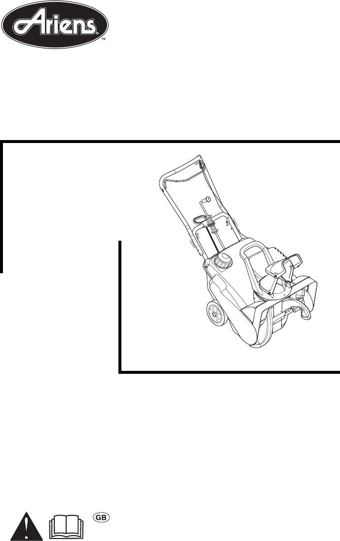
Owner/Operator ManualModels938017 - SS522EC938018 - SS722ECSno-Thro®03392200 5/08Printed in USAU.S. Patents5758436 and 5966846ENGLISH
GB - 101. Auger Clutch Bail2. Handlebar3. Discharge Chute Crank 4. Handlebar Wing Knob5. Spark Plug Access Cover6. Discharge Chute Handle7. Exhaust8.
GB - 11CONTROLS AND FEATURESSee figure 6 for controls and features locations.Ignition SwitchIgnition switch is operated by a removable key that has tw
GB - 12Discharge Chute DeflectorALWAYS position discharge chute deflector at a safe angle before starting engine.DO NOT throw snow any higher than nec
GB - 13STOPPING IN AN EMERGENCYImmediately release auger clutch bail to stop unit in an emergency. Stop engine, remove key and wait for all rotating p
GB - 14Tips for OperationSnow is best removed as soon as possible after a snow fall.To clear an area, run unit in an overlapping series of paths. For
GB - 15SERVICE POSITIONPlace unit on a flat level surface. DRIVE BELT REPLACEMENTRemove (Figure 8)1. Remove cowl.2. Disconnect extension spring on idl
GB - 16DISCHARGE CHUTE DEFLECTOR ADJUSTMENT If discharge chute deflector does not stay in position while throwing snow, adjust chute by tightening fas
GB - 173. Loosen belt finger and rotate until there is 1/32 – 1/16 in. (0.8 – 1.6 mm) gap between belt finger and drive belt.4. Tighten belt finger.5.
GB - 18SHORT TERMIMPORTANT: NEVER spray unit with high pressure water or store unit outdoors.Run with attachment clutch engaged a few minutes after ea
GB - 19TROUBLESHOOTINGPROBLEM PROBABLE CAUSE CORRECTIONEngine will not crank/start1. Key not in RUN position.2. Fuel tank empty.3. Clogged fuel filter
GB - 2Safety . . . . . . . . . . . . . . . . . . . . . . . . . . . . . 4Assembly . . . . . . . . . . . . . . . . . . . . . . . . . . 8Controls & F
GB - 20SPECIFICATIONSModel Number 938017 938018Description SS522EC SS722ECEngine - Tecumseh (Two-Cycle) TH139SA TH139SPEngine Power – hp (kW) at Maxim
ARIENS COMPANYGRAVELY® | STENS® | LOCKE® | NATIONAL® MOWER | BYNORM® | EVERRIDE® | GREAT DANE® Snow_200822Three-Year Limited Sno-Thro® WarrantyAriens
ARIENS COMPANYGRAVELY® | STENS® | LOCKE® | NATIONAL® | BYNORM® | EVERRIDE® | GREAT DANE® Snow_200823Limitations• Batteries are warranted only for a p
Ariens Company655 West Ryan StreetBrillion, WI 54110-1072920-756-2141Fax 920-756-2407www.ariens.com
GB - 3• Record Unit Model and Serial numbers here.• Record Engine Model and Serial number here.PRODUCT REGISTRATIONThe Ariens dealer must register the
GB - 4SAFETY ALERTSLook for these symbols to point out important safety precautions. They mean:Attention! Personal Safety Is Involved!Become Alert! Ob
GB - 5SAFETY DECALS AND LOCATIONSALWAYS replace missing or damaged Safety Decals. Refer to figure 2 below for Safety Decal locations.1. DANGER!• Read
GB - 6SAFETY RULESRead, understand, and follow all safety practices in Owner/Operator Manual before beginning assembly or operating. Failure to follow
GB - 7Understand:• How to operate all controls.• The functions of all controls.• How to STOP in an emergency.Before starting engine, disengage control
GB - 8If fuel is spilled on clothing, change clothing immediately.Before tipping unit up onto housing, remove fuel so no spills will occur. Ensure uni
GB - 9Discharge Chute Assembly1. Remove bolt and nut from rear of discharge chute (figure 4).2. Tip discharge chute up and install hardware just remov
More documents for Snow throwers Ariens 938018 - SS722EC

Related products and manuals for Snow throwers Ariens 938018 - SS722EC
 (25 pages)
 (32 pages) (5 pages)
(2 pages)
(36 pages)
(44 pages)
(33 pages)
(32 pages) (5 pages)
(2 pages)
(36 pages)
(44 pages)
(33 pages)
 (30 pages)
© 2020, manymanuals.com. All rights reserved. | 0.982 s |
 Manymanuals.com
 Manymanuals.de
 Manymanuals.fr
 Manymanuals.it
 Manymanuals.pl
 Manymanuals.cz
 Manymanuals.es
 Manymanuals-pt.com
Comments to this Manuals