Ariens 1336 Specifications
Browse online or download Specifications for Snow throwers Ariens 1336. Ariens 1336 Specifications User Manual
- Page / 36
- Table of contents
- TROUBLESHOOTING
- BOOKMARKS
- Sno-Thro® 1
- TABLE OF CONTENTS 2
- INTRODUCTION 2
- DELIVERY 3
- SAFETY RULES 4
- ASSEMBLY 7
- Deflector Remote 9
- CONTROLS AND FEATURES 11
- 926021, 022, 023 12
- OPERATION 13
- FILLING FUEL TANK 16
- PRE-START 17
- TO STOP IN AN EMERGENCY 17
- STARTING AND SHUT OFF 17
- SNOW REMOVAL 18
- TRAVELING 19
- TRANSPORT 19
- MAINTENANCE SCHEDULE 19
- Auger Shaft 20
- Terminals 21
- SERVICE AND ADJUSTMENTS 22
- DEFLECTOR REMOTE 23
- DISCHARGE CHUTE 23
- SPEED SELECTOR ADJUSTMENT 24
- ATTACHMENT CLUTCH/BRAKE 24
- ADJUSTMENT 24
- Extension 25
- Check Attachment Brake 26
- Check Belt Finger Clearance 26
- ATTACHMENT DRIVE BELTS 27
- REPLACEMENT 27
- FRICTION DISC REPLACEMENT 29
- BATTERY (926023, 500, 501) 29
- 022, 023) 29
- SERVICE PARTS 30
- ACCESSORIES 30
- TROUBLESHOOTING 31
- SPECIFICATIONS 32
- Ariens Limited 34
- Warranties 34
Summary of Contents
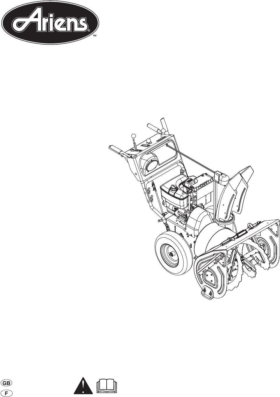
Owner/Operator ManualModels926016 – ST11528DLE926017 – ST9526DLE926021 – ST9526DLET926022 – ST11528DLET926023 – ST1332DLET926500 – ST1332DLE926501 – S
GB - 10Check Track Tension (926021, 022, 023)Check tracking of unit with the differential locked, and tension of tracks (see Track Tension Adjustment
GB - 111. Attachment Clutch Lever2. Speed Selector3. Deflector Remote Control 4. Chute Control 5. Traction Drive Clutch Lever6. Oil Fill/Dipstick7. Mu
GB - 121. Attachment Clutch Lever2. Speed Selector3. Deflector Remote Control 4. Chute Control 5. Traction Drive Clutch Lever6. Oil Fill/Dipstick7. Di
GB - 13CONTROLS AND FEATURESSee Figure 10 for all Controls and Features locations.Dual Handle Interlock When Attachment Clutch and then Traction Drive
GB - 14Choke Control Knob1. Choke Closed position: chokes off air to engine for easier start.2. Choke Open position: allows for normal operation.IMPOR
GB - 15Discharge Chute ControlIMPORTANT: If chute does not stay in set position, adjust as directed in SERVICE AND ADJUSTMENTS on page 22, or repair
GB - 16Drift Cutters(Figure 15)Drift cutters break up snow drifts that are taller than the auger housing and direct the snow into the auger. Store the
GB - 17To add fuel to fuel tank: 1. ALWAYS place unit in open or well-ventilated area.2. Stop engine and allow to cool.3. Clean Fuel Cap and surroundi
GB - 18Manual Start1. Turn discharge chute straight ahead.2. Make sure that the traction clutch and attachment drive clutch levers are fully disengage
GB - 19IMPORTANT: DO NOT overload unit capacity by attempting to clear snow at too fast a rate. Use slow speed to clear deep or hard packed snow.Tips
GB - 29SAFETY. . . . . . . . . . . . . . . . . . . . . . . . . . . . . . . . . . 3ASSEMBLY . . . . . . . . . . . . . . . . . . . . . . . . . . . . . .
GB - 20CHECK DUAL HANDLE INTERLOCK Without the engine running, press down (engage) both clutch levers. Release attachment clutch lever. Attachment clu
GB - 21CLEAN BATTERY 926023, 500, 501IMPORTANT: Battery is maintenance-free. Do not tamper with or attempt to open battery. See SERVICE AND ADJUSTMENT
GB - 22SCRAPER BLADEIMPORTANT: Damage to auger/impeller housing will result if blade wears down too far.Scraper blade is adjustable to compensate for
GB - 23NOTE: Insert the hair pin with the loop end on the left side of the chute rod so the control lever will cover its full range of travel.6. Align
GB - 24If chute does not rotate freely:Tighten the cable by loosening the upper adjustment nut, and then tightening the lower adjustment nut against t
GB - 253. With the attachment clutch disengaged, check that the attachment idler arm lightly touches the frame. See Figure 31.4. Tighten jam nut on th
GB - 262. Adjust attachment idler position. See Figure 34.a. Loosen idler adjustment nut.b. To increase spring extension, move idler closer to belts a
GB - 272. Replace the belt cover.TRACTION DRIVE CLUTCH ADJUSTMENTIf drive slips, adjust traction clutch to compensate for friction disc wear.To adjust
GB - 283. Remove hair pin under the control panel connecting the discharge chute rod from the chute rotation lever and slide the discharge chute rod f
GB - 294. Install new traction drive belt onto attachment pulley and engine sheaves.5. Pull the drive plate assembly toward the friction disc and tigh
GB - 3DELIVERYCustomer Note: If you have purchased this product without complete assembly and instruction by your retailer, it is your responsibility
GB - 30SHORT TERMIMPORTANT: NEVER spray unit with high pressure water or store unit outdoors.Run with attachment clutch engaged a few minutes after ea
GB - 31 TROUBLESHOOTINGPROBLEM PROBABLE CAUSE CORRECTION Engine will not crank/start.1. Fuel tank is empty.2. Fuel shut-off valve closed.3. Build up o
GB - 32SPECIFICATIONSModel Number 926016 926017 926021 926022DescriptionST11528DLE ST9526DLE ST9526DLET ST11528DLETEngine - TecumsehOH318SATecumsehOH
GB - 33SPECIFICATIONSModel Number 926023 926500 926501DescriptionST1332DLET ST1332DLE ST1336DLEEngine - TecumsehOH358SATecumsehOH358SATecu ms ehOH358
Ariens Company • 655 W. Ryan St. • Brillion, WI 54110-1072• (920) 756-2141 • www.ariens.com ALW2 - 61407Ariens Limited Warranties2-Year Limited Lawn a
Ariens Company • 655 W. Ryan St. • Brillion, WI 54110-1072• (920) 756-2141 • www.ariens.com ALW2 - 61407Exceptions, Limitations, ExclusionsThese warra
Ariens Company655 West Ryan StreetBrillion, WI 54110-1072920-756-2141Fax 920-756-2407www.ariens.com
GB - 41. WARNING!2. DANGER! 3. DANGER!SAFETY RULESRead, understand, and follow all safety practices in Owner/Operator Manual before beginning assembly
GB - 5Check for weak spots on docks, ramps or floors. Avoid uneven work areas and rough terrain. Stay alert for hidden hazards.DO NOT operate near dro
GB - 6ALWAYS shut off engine, remove key, and close fuel shut-off valve or drain fuel when transporting unit on a truck or trailer.Use extra care when
GB - 7PACKAGE CONTENTSASSEMBLYTools Required:•Pliers• Open-End Wrenches: 3/8, 7/16, 1/2, 9/16 in. and/or Adjustable Wrench• Tire GaugeUnfold Handlebar
GB - 84. Remove the cover from the gear assembly on the discharge chute.5. Release the lock teeth on the gear assembly with your finger and rotate the
GB - 910. Replace the gear cover removed in step 4.IMPORTANT: Rotate the discharge chute to the left when tightening the pedestal hardware to ensure c
Related products and manuals for Snow throwers Ariens 1336
 (24 pages)
 (42 pages)
 (13 pages)
(26 pages)
(13 pages)
(26 pages)
 (36 pages)
(40 pages)
(62 pages)
(19 pages)
(36 pages)
(40 pages)
(62 pages)
(19 pages)
© 2020, manymanuals.com. All rights reserved. | 1.824 s |
 Manymanuals.com
 Manymanuals.de
 Manymanuals.fr
 Manymanuals.it
 Manymanuals.pl
 Manymanuals.cz
 Manymanuals.es
 Manymanuals-pt.com
Comments to this Manuals