Ariens 911410-WAW 34 Specifications Page 12
- Page / 62
- Table of contents
- BOOKMARKS
- Wide Area Walk Mower 1
- PRODUCT REGISTRATION 3
- UNAUTHORIZED REPLACEMENT 3
- DEALER DELIVERY 3
- DISCLAIMER 3
- SAFETY ALERTS 4
- NOTATIONS 4
- PRACTICES AND LAWS 4
- REQUIRED OPERATOR 4
- TRAINING 4
- SAFETY DECALS AND 5
- LOCATIONS 5
- SAFETY RULES 6
- CARTON CONTENTS 9
- ASSEMBLY 10
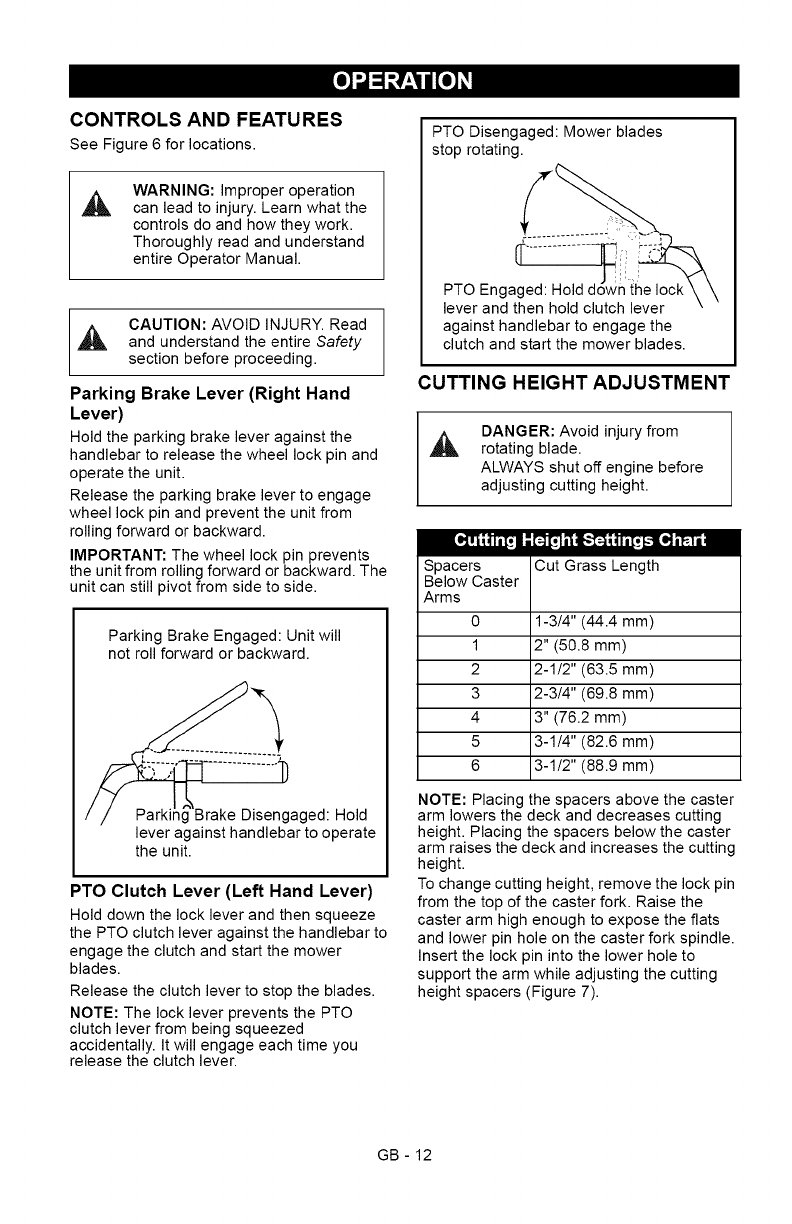
- CONTROLS AND FEATURES 12
- CUTTING HEIGHT ADJUSTMENT 12
- ...¢::....... GO 14
- FILLING THE FUEL TANK 14
- GASOLINE 14
- EMERGENCY STOPPING 15
- STARTING AND SHUT OFF 15
- Sharpen the Mower Blades 17
- BELT REPLACEMENT 20
- REPLACING MOWER BLADE 21
- SERVICING THE BATTERY 22
- 6.Replacebeltcover 23
- / 24
- P_'T__o];_[_,,,,_ 25
- ___o_,,,_ 26
- Two-Year Limited Lawn 27
- ARIENS COMPANY 28
- A WARNING A 29
- I1Eqi][_" 31
- •AnoteaquilosnQmerosdemodelo 32
- S[MBOLOS DE 8EGURIDAD 33
- NOTACIONES 33
- PRACTICA8 Y LEYES 33
- FORMACION REQUERIDA 33
- AL OPERADOR 33
- ETIQUETAS DE SEGURIDAD 34
- Y EMPLAZAMIENTO 34
- DE LAS MISMAS 34
- NORMAS DE SEGURIDAD 35
- CONTENIDO DE LA CAJA 39
- L'd 41
- CONTROLES Y FUNCIONES 42
- AJUSTE DE LA ALTURA DE CORTE 42
- / ....... de estacionamiento 44
- GASOLINA 45
- PARADA DE EMERGENCIA 45
- ARRANQUEYPARADA 45
- NOTA:Paraimpedirquelasuciedad 46
- LUBRICACION GENERAL 49
- REVISION DE LA BUJiA 49
- REVISION DE LA REFRIGERACION 49
- DEL MOTOR 49
- REVISION DEL SILENCIADOR 49
- 1.Graduador 2.Contratuerca 51
- Figura13 51
- Correa de la TDF 52
- RECOLOCACION DE LA CUCHILLA 53
- MANTENIMIENTO DE LA BATERiA 54
- Carga de la bateria 55
- PRECAUClON:EVITELAS 56
- I_,,,,___o,][o_]_,,,,_ 59
- Garantia limitada de dos a os 60
Related products and manuals for Lawnmowers Ariens 911410-WAW 34
 (60 pages)
 (35 pages)
 (32 pages)
(26 pages)
(28 pages)
(32 pages)
(26 pages)
(28 pages)
© 2020, manymanuals.com. All rights reserved. | 0.747 s |
 Manymanuals.com
 Manymanuals.de
 Manymanuals.fr
 Manymanuals.it
 Manymanuals.pl
 Manymanuals.cz
 Manymanuals.es
 Manymanuals-pt.com
Comments to this Manuals