Ariens 924 User Manual
Browse online or download User Manual for Gardening equipment Ariens 924. Ariens 924 User Manual
- Page / 72
- Table of contents
- BOOKMARKS
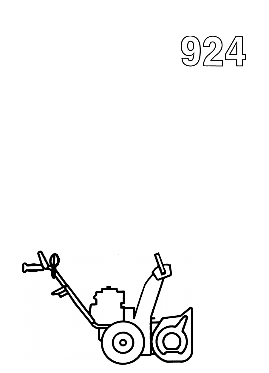
- Sno-Thro® 1
- Introduction 2
- Safety Precautions 3
- Special Tools 4
- Part No. 000123A 5
- Specifications 7
- Handlebars And Controls 10
- Handlebars and Controls 12
- Handelbars and Controls 14
- TO ENGINE ■ 17
- Speed Selector and Wheels 20
- Table of Contents 20
- List of Illustrations 20
- Speed Selector And Wheels 22
- Belt Drive 26
- Reduction Drive 32
- Friction Wheel Drive 38
- Friction Wheei Drive 39
- X 1" 40
- Auger/Impeller 42
- ¿^>,3 44
- Gear Case 48
- Cast Iron 50
- X 7/8 X 3/8 51
- Aluminum 52
- X 1-3/4 15 52
- 19 ' I 53
- Engine and Headlight 56
- Attachments 62
- DESCRIPTION 65
- N0. DESCRIPTION 65
Summary of Contents
ObriensSeries▲ SAFETY MESSAGE AThe product for which you have requested information or repiacement parts is not a current product. The repiacement mod
Handlebars And ControlsMECHANICAL INTERLOCKFigure 2-2: Handlebars and Controls2-2
Handlebars And ControlsITEMNO.DESCRIPTIONITEMNO.DESCRIPTION1Wheel Drive Clutch Lever37Cotter Pin 3/32 X 3/42Upper Handle Bar38Clutch Fork3Lock Nut 1/4
Handlebars and Controls1. Key2. Stiffener3. Wire4. Nut5. Washer6. Lower Handlebar7. Carriage Bolt 5/16-18 x 1-1/28. Key Switch9. Key Switch N
Handlebars and Controls1. Push Nut2. Pin3. Attachment Clutch Rod4. Setscrew5. Clevis6. Cotter Pin7. Chain8. Spring9. Rod Adapter10. Traction
2.6 Clutch Yoke and ForkHandelbars and Controls2.7 Traction Drive Clutch AdjustmentRemove locknut and adapter spacer holding spring assembly in clutch
Handelbars and Controls2.8 Mechanical Interlock AdjustmentAWARNING: With improper usage of unit, failure of interlock if unnoticed, could re
Handelbars and Controls2.10 Chute CrankSmooth and easy rotation of properly lubricated chute with crank (without binding) is obtained by
ELECTRICAL INTERLOCKHandlebars and ControlsWHITE TO ENGINE MAGNETO1. Switch Boot2. Wiring Harness3. Clip4. Shorting Wire5. Flange Whiziock Scre
Handlebars and ControlsEngine runs with interlock and/or traction clutch engaged. Engine must stop if both are disengaged with attachment clutch
Notes
A Message To Ariens Repair Manuai UserYour Ariens Dealer will be happy to supply any service or advice which may be required to keep y
Speed Selector and Wheels Table of ContentsPage3.1 Speed Selector...
Speed Selector and Wheelsf—j—If—\J—iV—a__rt__a--'1. Speed Selector2. Upper Shift Rod3. Nut4. Lower Shift Rod5. Shift Links6. Shift Links7.
Speed Selector And Wheels©-3-2
Speed Selector And WheelsITEMNO.DESCRIPTIONITEMNO.DESCRIPTION1Snap Ring Ext. 1/216Lower Shift Rod2Knob17Shift Arm Lever3Rod 18Frame4Extension Spring19
Speed Selector and Wheels3.1 Speed SelectorRemove cotter pin in upper rod and disconnect rod from pivot.Remove cotter in lower rod and d
Notes
Belt DriveTable of ContentsPage4.1 Introduction...
Belt Drive1. Pulley2. Attachment Pulley3. Idler4. Belt5. Engine Pulley6. BeltFigure 4-1: Belt Drive Assembly4-1
Belt Drive4-2
Belt DriveITEMNO.DESCRIPTIONITEMNO.DESCRIPTION9Taptite 1/4-20 x 1/231Washer 5/1610Washer 17/6432Idler11Belt Cover 33Bearing Spacer12Belt Finger34Cap S
Safety Alert Symbol And NotationsThe following safety notations are used throughout this manual to call attention to special information or operating
Belt Drive4.1 IntroductionAWARNING: Remove wire from spark plug before attempting any repair or adjustment procedures.When unit is tipped t
Notes
Reduction Drive Table of ContentsPage5.1 Introduction...
Reduction DriveFigure 5-1: Reduction Drive Assembly1. Idler Chain2. Hex Shaft3. Pinion Shaft4. Drive Spindle Housing5. Spindle6. Differential7.
Reduction DriveFigure 5-2: Reduction Drive5-2
Reduction DriveITEMNO.DESCRIPTIONITEMNO.DESCRIPTION1Taptite 1/4-20 x 3/831Pinion and Sprocket2Shaft Support32Bushing3Bearing Retainer33Zerk Fitting4Ba
Reduction Drive5.1 IntroductionAWARNING: Gasoline is highly flammable and its vapors are explosive. Handle with care.When unit is tipped to
5.7 Drive ChainsRemove link from chain and chain from sprocket.On continuous chain grind off end of rivet.When replacing chain, be sure retainer
Friction Wheel Drive Table of ContentsPage6.1 Introduction...
Friction Wheei Drive1. Hex Shaft2. Friction Disc3. Drive Plate4. Drive Spindle HousingFigure 6-1: Friction Wheel Assembly6-1
Special Tools000078 - Bearing Driver for Sno- Thro axle shaft and Sno-Thro gear case.000097 - Bearing Driver for Sno- Thro gear case flan
Friction Wheel DriveiTEMNO.DESCRIPTIONITEMNO.DESCRIPTION1Drive Plate16Roll Pin 5/32 X 1"2 Drive Disc Spacer17Bushing3Spindle 18Nylon Lock Nut 7/8
Friction Wheel Drive6.1 IntroductionAWARNING: Remove wire from spark plug before attempting any repair or adjustment procedures.When unit is tipped t
Auger/Impeller Table of ContentsPage7.1 Introduction...
Auger/Impeller1. Chute Crank2. Universal Joint3. Impeller4. Gear Case5. Scraper Blade6. Runner7. Auger Housing8. Auger9. Discharge Chute10.
Auger/Impeller¿^>,3Figure 7-2: Auger/Impeller7-2
Auger/ImpellerITEMNO.DESCRIPTIONITEMNO.DESCRIPTION1 Deflector 36Lock Nut 1/4-202Cap37Bushing3Knob 38Washer 1/24Chute Control Crank39Lock Washer 1/25Ha
Auger/Impeller7.1 IntroductionAWARNING: Remove wire from spark plug before attempting any repair or adjustment procedures.When unit is tipped to
Auger/ImpellerIf impeller brake shoe is not 1/16 to 1/8 inch from belt, disengage clutch, loosen attachment idler nut, reposition idler to compensa
Gear CaseTable of ContentsPage8.1 Introduction...
Gear Case1. Cast Iron Gear Case (Worm)2. Cast Iron Gear Case (Helicon)3. Aluminum Gear Case (Worm)Figure 8-1: Gear Case Assemblies8-1
IndexSectionSpecifications.Handlebars and Controls.Speed Selector and WheelsBelt DriveReduction DriveFriction Wheel Drive.Auger/Impeller.Gear Case.Eng
Gear CaseCast Iron
Gear CaseCast IronITEMNO.DESCRIPTIONITEMNO. DESCRIPTION1Roll Pin 5/16 X 1-3/418Dust Cap2Fan19Roll Pin 3/16 X 1-1/23Woodruff Key 3/16x7/8x3/820Gear Cas
Gear Case AluminumITEMNO.DESCRIPTIONITEMNO.DESCRIPTION1Roll Pin 1/4 X 1-3/4 15Bushing2Impeller16Bushing30-Ring17Washer 1"4Bushing18Groove Pin 5/1
Gear CaseCast IronFigure 8-4: Cast Iron Gear Case (Helicon Gear)19 ' IITEMNO.DESCRIPTIONITEMNO.DESCRIPTION1Roll Pin 1/4 X 1-1/412 Seal2Fan13 Gea
Gear Case8.1 IntroductionAWARNING: Remove wire from spark plug before attempting any repair or adjustment procedures.When unit is tipped to
Gear CaseInspect worm for burrs or black coloration. If either show up, replace shaft.To assemble make sure you replace the case gasket and make sure
Engine and Headlight Table of ContentsPage9.1 Engine Oil...
Engine and Headlight1. Engine2. Hex Cap3. Nipple4. Street Elbow5. Tube6. Hose Clamp7. Drain Lock8. Adapter9. Nut 5/16-1810. Lock Washer 5/16
Engine and HeadlightAriens Dealers will provide any service which may be required to keep your Sno-Thro operating at peak efficiency. Should en
Engine and Headlightd.6 HeadlightInstall headlight bracket (level with floor) on right handlebar with hardware provided (Figure 10-1).NOTE; Tw
Engine and Headlight9.7 Add-On AlternatorRemove rewind starter keps nuts and starter from engine. (Note location of rewind starter handle).Remove pu
Notes
AttachmentsTable of Contents10.1 Caster Wheels...10.2 Rotary Mower Lubrication.Page10-310-7List of IllustrationsPage10-1: Rotary B
Notes10-1
Attachments81 1 0 /V \J0p%82^m 1s'aFigure 10-1: Rotary Brush10-2
AttachmentsITEMN0.DESCRIPTIONITEMN0. DESCRIPTION1Nut 5/16-1844Roll Pin 3/16 X 1-1/22Lock Washer 5/1645U-Joint3Set Screw 1/4-2046Drive Shaft4Bearing 47
Attachments
AttachmentsITEMN0.DESCRIPTIONITEMNO.DESCRIPTION1Cotter Pin 1/8 X 1"45Pinion Shaft2 Lockwasher 3/8-.145 x .11546Snap Ring3Ball Bearing47Bearing Sp
AttachmentsFigure 10-3: Rotary Mower Pan
AttachmentsITEMN0.DESCRIPTIONITEMN0. DESCRIPTION1Cotter Pin 1/8 X 1"30Front Lift Adapter2Shoulder Bolt31Mower Pan3Yoke32Plate4 Link Rod33Retainer
SpecificationsLength... 60-63 inchesHeight...
Ask your dealer for information about these other fine Ariens products;ObriensAriens Company 655 W. Ryan Street Brillion,WI 54110-1098
Handlebars and Controls Table of ContentsPage2.1 Upper Handlebar Panel and Key Switch.....
Handlebars and Controls1. Lower Handlebar2. Speed Control Lever3. Attachment Clutch Handle4. Key Switch5. Chute Crank6. Upper Handlebar7. Wheel
Related products and manuals for Gardening equipment Ariens 924
 (30 pages)
(167 pages)
(30 pages)
(167 pages)
 (52 pages) (23 pages)
© 2020, manymanuals.com. All rights reserved. | 0.636 s |
 Manymanuals.com
 Manymanuals.de
 Manymanuals.fr
 Manymanuals.it
 Manymanuals.pl
 Manymanuals.cz
 Manymanuals.es
 Manymanuals-pt.com
Comments to this Manuals