Ariens Path-Pro 136E User Manual
Browse online or download User Manual for Garden tools Ariens Path-Pro 136E. Ariens Path-Pro 136E User`s manual
- Page / 80
- Table of contents
- BOOKMARKS
- Series 920 1
- Safety Information 2
- Your Program 3
- Contents 4
- Figures, Tables and Charts 5
- Chapter 1 6
- Starting out with the 6
- Watlow Series 920: 6
- Packing List 7
- How to Open the 920 8
- How to Set the DIP Switches 8
- User’s Manual 9
- Operating 10
- Chapter 11
- Keyboard Area 13
- Where To Go From Here 13
- A Brief Overview 14
- Enter Real Time of Day 14
- Before Entering Your Program 15
- Programming. File 1 15
- Step 4 must be 16
- Editing Your Program 17
- Adding an AUTOSTART Step Type 17
- Running Your Series 920 19
- Chapter 4 20
- How to Check for Ground Loops 22
- Noise Suppression Devices 22
- Available from Watlow 22
- C.M.Line Filter 23
- Installation Information 24
- Installation Procedure 24
- How to Wire the Series 920 25
- Power Wiring 26
- T.C. Compensation 27
- Load from 30
- Temperature Conrol 32
- How to Tune the Series 920 33
- Series 920 User’s 34
- Chapter 6 36
- How To Program The Series 920 36
- Event Outputs 37
- Guaranteed Soak 37
- The Four 38
- JUMPLOOP 38
- Rules to Follow 39
- SYSTEM Menu 40
- .:.:.:.: 41
- SETUP Menu 42
- Represents the 45
- PROGRAM Menu 49
- StepType 50
- To Program 52
- 920, Chapter 6 52
- Chart I- Master Step Chart 53
- Chapter 7 54
- Alarm Types 55
- The Operating Band 56
- Alarm Limits 57
- Clearing An Alarm Message 58
- An Alarm And The State 58
- The Alarm Relay 58
- Appendix 59
- Series 920 Specifications 59
- 920 User’s Manual 60
- 61
- Type J, K, or T 62
- Reference Compen 62
- Equipment Required 63
- Setup and Calibration 63
- @)(sJ(g; 64
- Glossary 67
- Accepts the sensor input and 68
- Isolation: 70
- ON/OFF control: 71
- WATLOW Series 920 73
- Manual 73
- Thermal System: 74
- Safety Information, 2 76
- Warranty Information 77
- Returning Merchandise 77
- Shipping Claims 77
- Series 920 Error Codes/Alarms 78
- Clearing an Error Code 79
- How to Clear an Alarm Code 79
- Series 920 Quick 80
- Reference 80
Summary of Contents
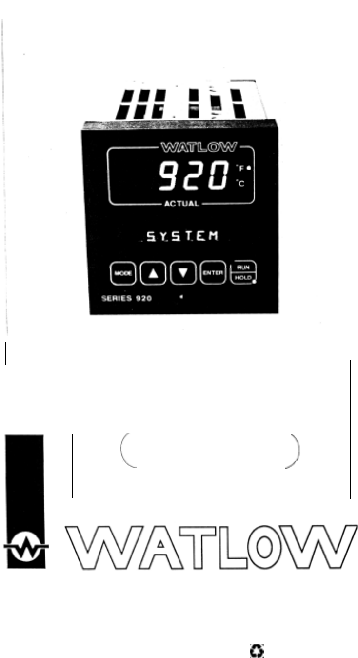
Series 920Microprocessor-BasedRamping ControlUser’s ManualWatlow Controls, 1241 Bundy Blvd., Winona, MN 55987, Phone: 507/454-5300, Fax: 507-452-4507W
Overview of the Three Operating ModesFigure 4 -Overview of theSeries 920OperatingBefore getting into the details of the Series 920s keys and displays,
Chapter 2How to Use the Keys and DisplaysThis chapter will show you the Series 920 front panel, and the function of eachdisplay, key and LED. Figures
Use the following figures to learn the nature and function of the Series 920skeys and displays.Figure 5 -Series 920 FrontPanel Information.Actual and
Keyboard AreaFigure 7 -DOWN KeyActs opposite the UPkey. Decreases thevalue in the alpha-numeric display. A lighttouch decreases theMODE KeyThis key st
Chapter 3m WARNING:Doing a cold startwill cause all setupparameters and filesto be lost. DO NOTput DIP switch #1 inthe ON positionunless all user-prog
24.J5.6.7.Use the UP/DOWN keys to place hours into the display. The display will flashuntil you press ENTER.Press MODE to continue to the MIN paramete
Table 2 -Series 920Ramp and SoakProgram.JNOTE:Step 4 must beentered as a stepeven though itdefaults to a STOPstep.4.Press the MODE key. Use the UP/DOW
Editing Your ProgramLet’s try editing the program by expanding it with another ramp and soak step andadding a jump loop. We’ll jump to Step 1 and repe
LlNKing FilesTable 5 -LlNKing toAnother File.The Series 920 enables you to link files together. The LINK step allows you to link thelast step of a pro
WAITFOR Process Variable (WPV). When equal, the HOLD LED stops flashing.Your program then continues to the last step, a STOP step, and HOLD S again.T
First...Starting OutFront PanelRunning a Programlnstall/WireTuneProgrammingAlarmsHow to Use Alarms, Chapter 7.AppendixSpecificationsGlossaryCalibratio
Chapter 4How to Install and Wire the Series 920This chapter tells you how to install the Series 920. All mounting and wiringinformation is right here
DefinitionsGround Loop - A condition created when two or more paths for electricity arecreated in a ground line, or when one or more paths are created
How to Check for Ground LoopsTo check for ground loops, disconnect the ground wire at the ground termina-tion. Measure the resistance from the wire to
Keep filters 12inches (304.8mm) orless from thecontrol. MinimizeJthe line distance1where noise can beLlL2GroundD.M. Line FilterControlLlC.M. Line Filt
Installation InformationnT0CAUTION:The front panelscrew turns 90°only. Do not applyexcessive force orturn the screw morethan 90°.Figure 12 -Series 920
(23.37mm)1 &-BezelMounting Brackett3.56 ± 0.015(90.42mm3 ±0.381Your PanelThickness0.06 to 0.25(1.524 to 6.35mm)3.622 to 3.653(92.00 to 92.79mm)Pan
01 WARNING:To avoid potentialelectric shock, useNational ElectricCode safety prac-tices when wiringand connecting thisunit to a powersource and toelec
Input Options: Terminals 1 - 8 Apply One Input OnlyT.C. CompensationRTD kl For RTD input, useTerminals 1,2 and 3.l For 0-5VDC, 0-20mAor 1-5VDC, 4-20mA
Output #1 Option B, Terminals 22 - 24Figure 18 -Output 1, S.S. Relay,Option "B", WiringDiagram.Model#92OA-_ B _ _-_000i!S.S.m,moutput #1 t
Output #1 Option D, Terminals 22 - 24Model #92OA-_ D_ _-_000Output #1 to;~~~~~~~~~~~~_~_~_______,i MechanicalI: Relay::tII:::I:I.1I:l+:Load from6A SPD
Page6677889101011111112131314141415151616171718I8191920202021222222242425262727283032ItemStarting out with the Watlow Series 920 - Chapter 1General De
Output, #l Option F, Terminals 22 - 241NOTE:Current for the4-20mA loop issourced internal tothe control.Use ungroundedsensors only.Figure 22 -output 1
Output #2 Option C, Terminals 14 - 16Model #920A- _ _ C - _ 000Figure 25 -Output 2S.S. Switch,Option "C",Wiring Diagram.Output #2 toLoad fro
System Wiring ExampleFigure 27 -System WiringThis example shows a typical Series 920 wiring scheme.it represents only oneof many output configurations
Chapter 5How to Tune the Series 920This chapter will explain tuning the Series 920 to the system it controls.Recommended Tuning ReferenceThere are a n
TuningFor optimum control performance, tune the 920 to a thermal system. The tuningsettings here are meant for a broad spectrum of applications; your
30°F, or 11° to 17°C. Observe the system’s approach to SP. If the loadtemperature overshoots SP, increase RT to 2.00 minutes.Then raise SP by 20 to 30
Chapter 6How To Program The Series 920This chapter will enable you to set up the Series 920 quickly and easily.It willexplain why it’s a good idea to
Event OutputsAnother feature of the Series 920 is its capability for two event outputs. An“event output” is simply a pre-programmed ON/OFF event per p
The Four JUMPLOOP TypesThe Series 920 gives you the capability to perform four basic jumploop types inyour programming. The backward jump, foward jump
Nested LOOPA “Nested” loop is a jump loop within a loop. You will be forced to a step eitherforwards or backwards from your present location. When nes
TuningProgrammingAlarmsAppendixTerminologyQuick ReferencePageItem33333333343535How to Tune the Series 920 - Chapter 5Recommended Tuning ReferenceUsing
Figure 29 -SYSTEM Key FlowJNOTE:Shaded parametersmay not appear onyour control. Theseparameters aredependent on howyour control isconfigured. SeePage
Table 8 -SYSTEM Prompts and Description.Make photocopies, keeD original clean:CLR ALARMDisplays the current alarm.1-2RETURNPress the ENTER key to retu
SETUP MenuWhile in the HOLD mode, press the MODE key until you see SETUP, pressENTER. These parameters are to setup the personality of your Series 920
PromptDescriptionACCESS = (0) CALIBRangeDefaultYour SettingsTo enter CALIB parameters, use ACCESS (0) and ENTER.Tl XX:XX Read only. Displays the Real
1NOTE:Changing these parameter values will default other parameters andclear all programmed files. See Page 47 for details.LOCKEnter the Front panel L
One of three main level operating menus.From the SETUP menu, you can setup orchange system-operating parameters such as real time, high/low range, ala
The heating cycle time usually expressed in seconds for a controller to complete one ON/OFF cycle. Time between successive turn ons. This parameter wi
From RETURN, you can go back to the SYSTEM prompt by pressing the ENTER key, orreturn to ACCESS (3) menu by pressing the MODE key.In the SETUP menu, A
RETURN 1Determines whether the alarm type for Auxiliary Output 1 will be a process alarm or a deviationalarm for the Series 920. This parameter will n
PROGRAM MenuFrom the Program menu, you can create your files. There can be up to tenprofiles; consisting of a total of 99 steps. You can only choose o
Figures, Tables and ChartsPage.689101212131923232324252526272728282929303030313132374042495555575762636466ItemSeries 920 Input and Output OverviewHow
Table 10 -PROGRAM Promptsand Description.1NOTES:The Series 920 leaves the factory programmed for a warm start. STOPsteps appear as a defautt until you
EIlIrEzq~~.~~~:+. . . . . . ..?.. . . . . . . . :... ..z..One of three main level operating menus. From the PROGRAM menu, you can enter orview step t
[RETURN 11 LINKIOne of six step types under the PROGRAM menu allowing you to link on8 file to another.[RETURN 1The number of times that the Series 920
Chart I- Master Step ChartMake photocopies, keep original clean.Step # √◊ Step Type Values Time EventsON or OFFL-l SETPOlNT SPiHRMNSECEV1Ev2RATEs $‘l’
Chapter 7How To Use the Series 920 AlarmsOne of the most versatile features of the Watlow Series 920 is its capability foralarms. The alarms can be au
Alarm TypesThere are three Alarm Types for each alarm. ALTYPl and ALTYP2 are theprompts for Alarm 1 and Alarm 2, respectively. The choices are:Process
The Operating BandNow we need to set the alarm limits. In doing so, you’ll define an “operatingband” where you want system temperature (or your contro
Alarm LimitsYou can set up alarm bands with the two available alarms. Each of the twoalarms has a high and a low limit point, indicated by the ‘I” or
Alarm function is either “latching” or “non-latching.” Latching is a means of“saving” indication of an alarm event for the operator to clear manually.
AppendixSeries 920 SpecificationsControl Mode.Microprocessor-based, user selectable modes..Single input, dual control outputs, dual auxiliary outputs.
Figurel-Series920 Inputoutput Overview6SelectabRTD, T/CProcessandChapter 1 Starting out with theWatlow Series 920:A Microprocessor-Based ControlDual P
l Offset of input signal, ±90°F (±50°C), ±50 PVU’s, front panel adjustable±9.0°F (±5.0°C) for 0.l° units.°F, °C, or process variable units are user
Series 920 Model Number BreakdownControlSeries920 =Input2 =3=4=#1 outputB =c =D =E=F=#2 outputA =B =c =D =|9|2|O|A|-|Single channel, microprocessor ba
J, K, & T Thermocouple Field Calibration ProcedureEquipment Requiredl T/C calibrator set at 0°C/32°F ORType “J”, “K”, or “T” Reference Compensator
R, S, & B Thermocouple Field Calibration ProcedureEquipment RequiredlType “R” Reference Compensator with reference junction at0°C/32° F ORT/C cali
RTD Field Calibration ProcedureFigure 38 -Decade ResistanceBox-to-Series 920Connection DiagramEquipment Requiredl 100 ohm precision decade resistance
6.Press the MODE key until the HOF XX.XX parameter appears on thealphanumeric display. (The decimal point will not appear on the display ofyour contro
Process Field Calibration ProcedureFigure 39 -Voltage/CurrentSource to Series 920Connection DiagramEquipment Requiredl4-1/2 digit, digital voltmeter (
GlossaryThis glossary includes general thermal system control terms.ACCESS( ):Actual display data:Alarm:ALTYP1 :ALTYP2:Antireset:Automatic Prompts:AUT
CALIB:C/F/U:Closed loop:CLR FILE:Cold junction:Cold junctioncompensation:Cold start:COM:COM ID:CT C:CT H:Cycle time:DAY:DB:Dead band:A temperature ban
Deviation:The difference between the value of the controlled variable andthe value at which it is being controlled.Default parameters:The parameters,
The Series 920 is a PID controller. You may input two complete sets of PIDparameters on the front panel for heat/cool applications. This includes rate
HOUR:Hysteresis:Hunting:IN:Input:Integral:Isolation:JC:JS:JUMPLOOP:LAT:LINK:LOCK:LOPWR:The HOUR parameter has three meanings, depending uponwhich menu
MANUAL:MN:Offset:ON/OFF control:Open loop:Operating band:OUT:Output:Overshoot:PB C:PB H:P control:Parameter:Proportioning control.A physical property
PID:PID control:Proportioning control with auto-reset and rate.PRG:setThis parameter determines whether theramp as a function of time or ramp rate.poi
RS H:RT:Represents the rate at which the set point changes in a giventime.RT C:The Rate (derivative) Cooling function detemined by how fastthe error b
SYSTEM:Switchingsensitivity:Thermal System:Thermocouple:Thermocouple breakprotection:Three modecontrol:TITime proportioningcontrol:Triac:Solid state s
A BAccuracy, 60Actual and Alphanumeric Display Area, 12, Fig. 6Alarms,Clearing, 41,45,58,78Codes, 79Configuration, 54.Definition, 67Function, 58Limits
Nested Loop, 39NLAT, 48Alarms, 58No Output, 30, Fig. 23Noise, Suppression Device Ratings, 22, Table 7Open the 920, How to, 8, Fig. 2Operating,Band, 56
Warranty InformationThe Watlow Series 920 is warranted to be free of defects in material andworkmanship for 36 months after delivery to the first purc
Series 920 Error Codes/AlarmsER1 Error Codes and Actions910111213141516202122Internal RAM failure; consult factory.External RAM failure; consult facto
Series 920 Response to Error CodesER1 Codes Shut Down OutputsThe Series 920 will shut down its outputs wheneveran ER1 code occurs. An ER1 code usually
How to Open the 920 A70CAUTION:The front panelscrew turns 90°only. Do not applyexcessive force orturn the screw morethan 90°.Figure 2 -How to Open the
Series 920 Quick ReferenceMain Menu@- To SYSTEM Menu- To PROGRAM Menu- To SETUP MenuSYSTEM MenuTo SYSTEM PromptPROGRAM MenuTo SYSTEMWatlow Controls, 1
DIPFunction NormalTable 1 -SW# OperatingDIP SwitchONOFFPositionSelection.1 Cold Start Warm Start OFF2Not UsedNot UsedOFF3Tenths of units displayedN
Related products and manuals for Garden tools Ariens Path-Pro 136E
 (40 pages)
(44 pages)
(2 pages)
(40 pages)
(44 pages)
(2 pages)
 (42 pages)
 (42 pages)
(8 pages)
(41 pages)
(32 pages)
(42 pages)
(8 pages)
(41 pages)
(32 pages)
© 2020, manymanuals.com. All rights reserved. | 0.352 s |
 Manymanuals.com
 Manymanuals.de
 Manymanuals.fr
 Manymanuals.it
 Manymanuals.pl
 Manymanuals.cz
 Manymanuals.es
 Manymanuals-pt.com
Comments to this Manuals