Ariens 927069-14532 Specifications Page 1
Browse online or download Specifications for Garden tools Ariens 927069-14532. Ariens 927069-14532 Specifications User Manual
- Page / 26
- Table of contents
- TROUBLESHOOTING
- BOOKMARKS
- Rear-Engine Rider 1
- TABLE OF CONTENTS 2
- INTRODUCTION 2
- DISCLAIMER 3
- SAFETY ALERTS 3
- NOTATIONS 3
- SAFETY DECALS AND 3
- LOCATIONS 3
- 1. Danger! 4
- 2. Hot Surfaces! 4
- SAFETY RULES 5
- ASSEMBLY 8
- CONTROLS AND FEATURES 9
- OPERATION 10
- FILLING FUEL TANK 11
- STOPPING IN AN EMERGENCY 11
- STARTING AND SHUTTING OFF 11
- OPERATING MOWER 12
- MOVING THE UNIT MANUALY 12
- FOR BEST PERFORMANCE 13
- SEAT ADJUSTMENT 13
- TRANSPORTING UNIT 13
- MAINTENANCE SCHEDULE 14
- SERVICE AND ADJUSTMENTS 15
- LEVELING MOWER DECK AND 16
- ADJUSTING MOWER DECK 16
- Adjusting Mower Deck Pitch 17
- MOWER BLADE REPLACEMENT 18
- SHARPENING MOWER BLADE 18
- Servicing the Battery 18
- FRONT WHEEL ALIGNMENT 19
- HYDROSTATIC BELT 20
- REPLACEMENT 20
- PTO BELT REPLACEMENT 21
- TROUBLESHOOTING 22
- SERVICE PARTS 23
- SPECIFICATIONS 24
- 2-Year Limited Warranty 25
Summary of Contents
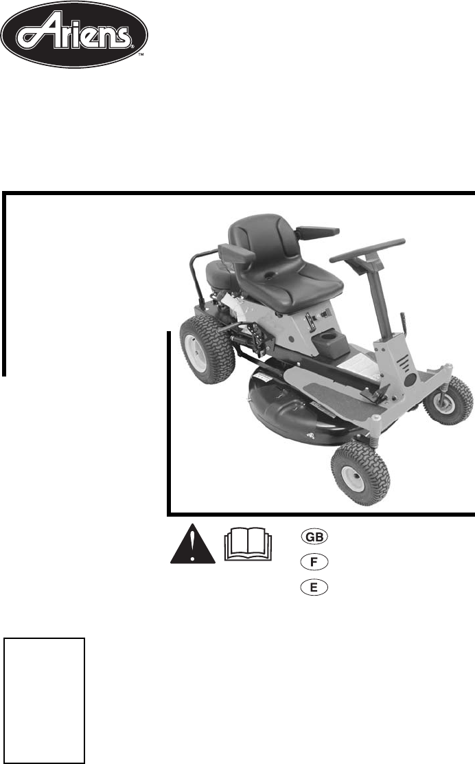
Owner/Operator ManualModels927067 - 10528927069 - 14532Rear-Engine Rider02792300 10/04Printed in USATransfer model & serial number label from prod
GB - 10Controls And FeaturesSee figure 3 for all controls and features locations.Safety Interlock SystemPerform the following tests to ensure the safe
GB - 11Forward and Reverse PedalPress front of pedal down to move unit forward.Press rear of pedal down to move unit backward.Remove foot from pedal t
GB - 123. Turn ignition key to start position and release once engine has started.4. After engine starts, set throttle lever to fast position.IMPORTAN
GB - 13SEAT ADJUSTMENT1. Tip seat forward (see TIPPING THE SEAT FORWARD on page 15).2. Loosen mounting hardware and slide seat forward or backward to
GB - 14IMPORTANT: Proper maintenance can prolong the life of unit. The following chart shows the recommended service schedule. Refer to the maintenanc
GB - 15TIPPING THE SEAT FORWARDPull out detent pin, pull seat back, and then lift seat out of seat retainer slots and place seat on frame and steerin
GB - 16LEVELING MOWER DECK AND ADJUSTING MOWER DECK PITCHAdjust on a level surface, with tires inflated to correct air pressure (see SPECIFICATIONS on
GB - 17Adjusting Mower Deck PitchNOTE: The front blade cutting height should be 1/16 – 3/8 in. (1.59 – 9.53 mm) lower than the rear blade cutting heig
GB - 18MOWER BLADE REPLACEMENTRemove (figure 15)1. Place mower lift lever in the highest position.2. Block mower blade to prevent rotation.3. Remove m
GB - 193. Remove battery hold-down bracket and cross brace.4. Remove battery from unit.Install (Figure 17)1. Install battery on unit.2. Install cross
GB - 2SAFETY . . . . . . . . . . . . . . . . . . . . . . . . . . 3ASSEMBLY. . . . . . . . . . . . . . . . . . . . . . . . 8CONTROLS AND FEATURES .
GB - 20• The minimum engagement of thread for both tie-rods is 1/4 in. (0.635 cm).Adjust (Figure 18)1. Remove tie-rod(s) from spindle(s).2. Loosen jam
GB - 21PTO BELT REPLACEMENTRemove (Figure 20)1. Lower mower deck to the ground.2. Pull idler towards the outside of the unit and remove PTO belt from
GB - 22TROUBLESHOOTINGPROBLEM PROBABLE CAUSE CORRECTIONEngine will not crank/start. 1. Safety interlock system is not engaged or is faulty. 1. Check s
GB - 23Unit moves with engine off and parking brake engaged. 1. The parking brake needs adjustment. 1. Contact your Ariens Dealer. 2. Faulty parking b
GB - 24SPECIFICATIONSModel Number 927067 927069Description 10528 14532EngineType Single Cylinder Briggs & StrattonEngine Power – hp (kW) @ Max RPM
GB - 25Ariens Company warrants to the original purchaser that consumer products manufacturedby Ariens Company will be free from defects in material an
Ariens Company655 West Ryan StreetP.O. Box 157Brillion, WI 54110-0157Phone: 920-756-2141Fax: 920-756-2407www.ariens.com
GB - 3Before Attempting To Operate Your Unit1. Make sure all assembly has been properly completed.2. Understand all Safety Precautions provided in the
GB - 41. Danger!2. Hot Surfaces!Figure 2OA001643215Read the operator’s manual.Keep children and others away from unit while operating.Never direct dis
GB - 53. Danger!4. Warning!5. Caution!SAFETY RULESIf unit is to be used by someone other than original purchaser; loaned, rented or sold, ALWAYS provi
GB - 6NEVER allow anyone to operate this unit when their alertness or coordination is impaired.Wear adequate safety gear, sturdy shoes, and protective
GB - 7This product is equipped with an internal combustion type engine. DO NOT use unit on or near any unimproved, forest-covered or brush covered lan
GB - 8TOOLS REQUIRED• Adjustable wrench• Petroleum jelly or dielectric grease.UNPACK UNITRemove unit and all other components from the shipping contai
GB - 91. Seat2. Steering Wheel3. Parking Brake4. Forward and Reverse Pedal5. Mower Deck6. Mulch Cover / Discharge Chute (Unit shown with mulch cover i
Related products and manuals for Garden tools Ariens 927069-14532
 (45 pages)
 (23 pages)
(40 pages)
(44 pages)
(2 pages)
(23 pages)
(40 pages)
(44 pages)
(2 pages)
 (42 pages)
 (42 pages)
(8 pages)
(41 pages)
(32 pages)
(42 pages)
(8 pages)
(41 pages)
(32 pages)
© 2020, manymanuals.com. All rights reserved. | 1.270 s |
 Manymanuals.com
 Manymanuals.de
 Manymanuals.fr
 Manymanuals.it
 Manymanuals.pl
 Manymanuals.cz
 Manymanuals.es
 Manymanuals-pt.com
Comments to this Manuals