Ariens 927046-056 User Manual Page 15
- Page / 36
- Table of contents
- BOOKMARKS
- TABLE OF CONTENTS 2
- SECTION 1 - INTRODUCTION 3
- SECTION 2 - SAFETY 4
- 2.9 SAFETY RULES 5
- SECTION 3 - SPECIFICATIONS 7
- 4.1 CONTROLS AND FEATURES 12
- 4.2 SERVICE POSITIONS 13
- 4.3 FILLING THE FUEL TANK 13
- 4.4 GENERAL LUBRICATION 13
- 4.5 MOWER BELT ADJUSTMENT 14
- 4.6 CLUTCH AND BRAKE 14
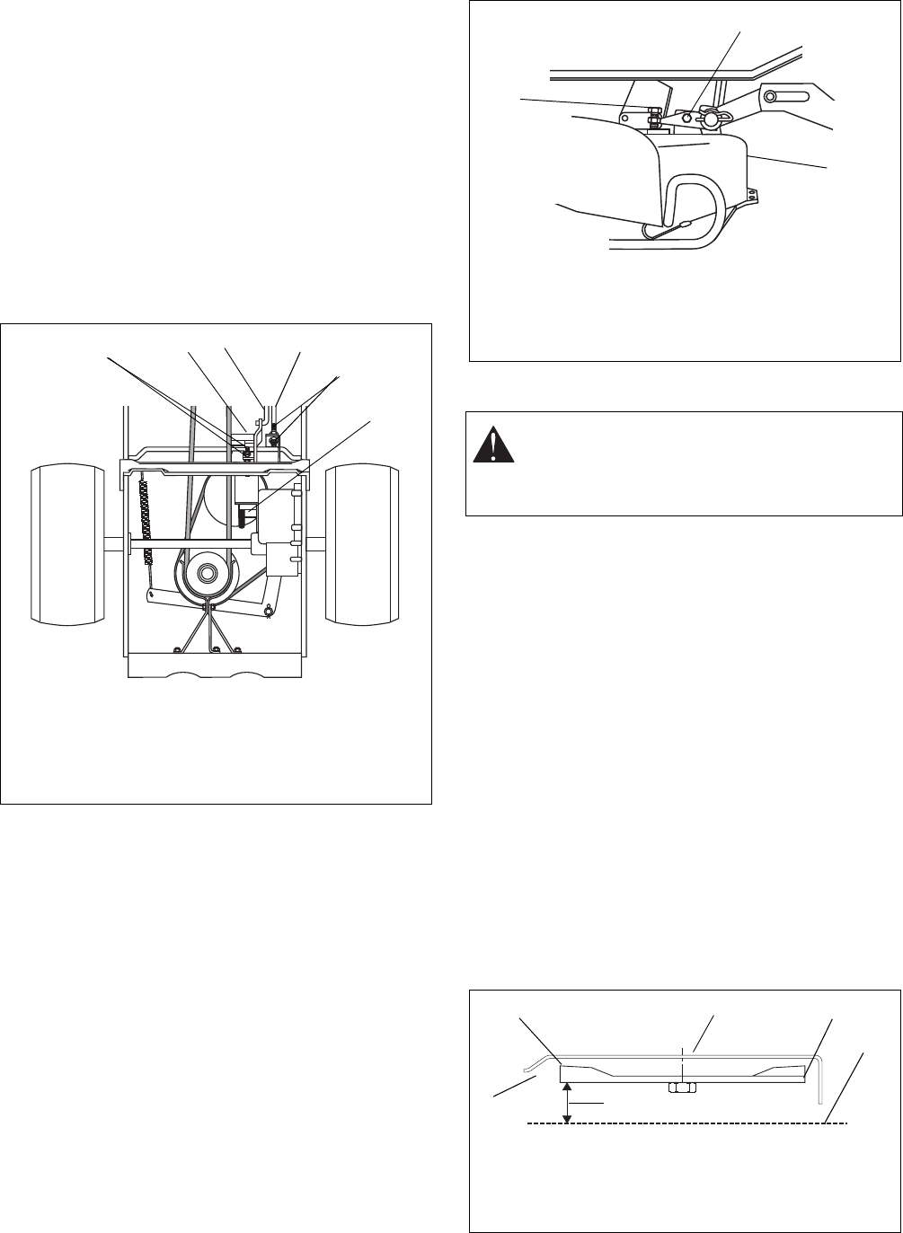
- 4.7 MOWER PAN 15
- 4.8 ANTI-SCALP ROLLERS 16
- 4.9 VENTS 16
- 4.10 PINION AND STEERING 17
- ADJUSTMENT 17
- 4.11 TIRES 17
- SECTION 5 - ENGINE 18
- 5.2 ENGINE OIL 19
- 5.3 CHANGING OIL 19
- 5.4 AIR CLEANER 19
- 5.5 SPARK PLUG 20
- 5.6 MUFFLER 20
- 5.7 ENGINE REMOVAL 20
- 5.8 ENGINE REPLACEMENT 20
- SECTION 6 - MOWER DECK 22
- 6.4 MOWER PAN REMOVAL 23
- ENGAGEMENT & CLUTCH/BRAKE 23
- To Remove Cowling 24
- 6.6 MOWER SPINDLE REMOVAL 25
- 7.1 STEERING SHAFT GEARS 26
- 7.2 SPEED SELECTOR 27
- SECTION 8 - BRAKE AND CLUTCH 28
- SECTION 9 - DRIVE TRAIN 29
- 9.1 GEAR CASE DISASSEMBLY 30
- 9.3 GEAR CASE REPLACEMENT 30
- Friction Wheel Wear Guide 31
- SECTION 10 - BAGGER 32
- 10.3 LOWER BOOT INSTALLATION 33
- SECTION 11 - ELECTRICAL 34
- Battery Electrolyte First Aid 35
- Battery Charger 35
- Jump Starting 35
© 2020, manymanuals.com. All rights reserved. | 0.668 s |
 Manymanuals.com
 Manymanuals.de
 Manymanuals.fr
 Manymanuals.it
 Manymanuals.pl
 Manymanuals.cz
 Manymanuals.es
 Manymanuals-pt.com
Comments to this Manuals