Ariens 891003 Specifications Page 10
- Page / 32
- Table of contents
- BOOKMARKS
- HD Series Bagger 1
- TABLE OF CONTENTS 2
- INTRODUCTION 2
- Attention! 3
- Personal Safety Is Involved! 3
- Become Alert! 3
- Obey The Message! 3
- 1. WARNING! 3
- ASSEMBLY 8
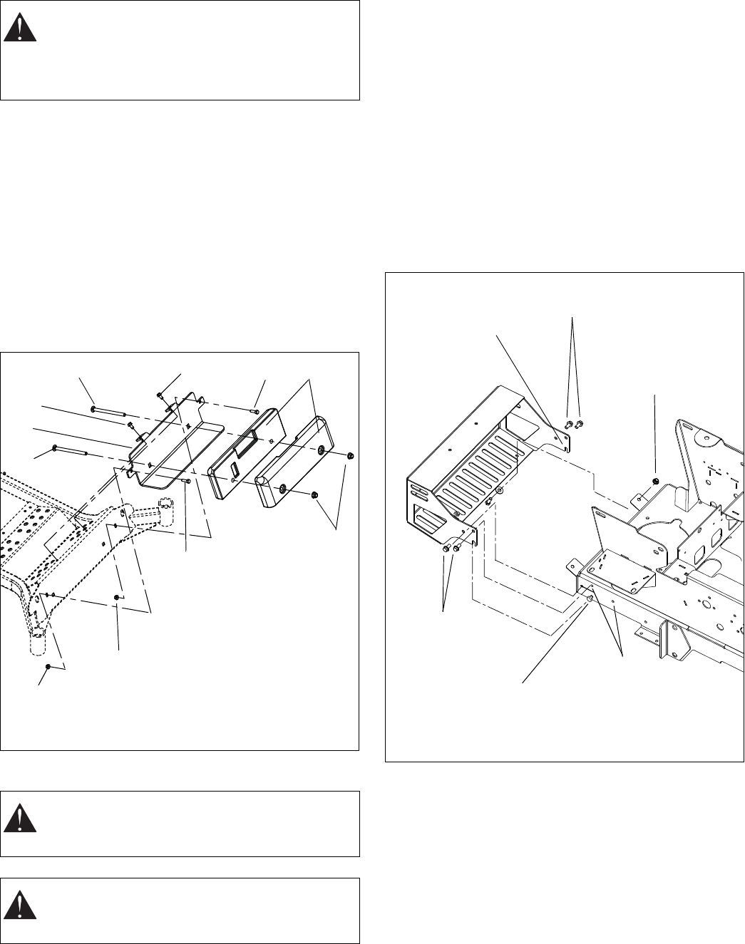
- INSTALL COUNTERWEIGHTS 10
- INSTALL BAGGER MOUNT 10
- INSTALL BAGS 13
- INSTALL BLOWER ASSEMBLY 13
- INSTALL HOSE 14
- Removing Bagger Kit 15
- OPERATION 16
- MAINTENANCE SCHEDULE 17
- MAINTENANCE 17
- TROUBLESHOOTING 18
- SPECIFICATIONS 18
- PARTS LIST 19
- BLOWER ASSEMBLY TO MOWER DECK 20
- BLOWER ASSEMBLY 22
- BLOWER ASSEMBLY (CONT.) 23
- MOUNTING ASSEMBLY 24
- MOUNTING ASSEMBLY (CONT.) 25
- BAGGER COVER ASSEMBLY 26
- BAGGER COVER ASSEMBLY (CONT.) 27
- COUNTERWEIGHT ASSEMBLY 28
- Two-Year Limited Lawn and 29
- Garden Consumer Ride-On 29
- Warranty 29
- Exceptions and Limitations 30
- Disclaimer 30
Related products and manuals for Air blowers/dryers Ariens 891003
 (32 pages)
© 2020, manymanuals.com. All rights reserved. | 0.970 s |
 Manymanuals.com
 Manymanuals.de
 Manymanuals.fr
 Manymanuals.it
 Manymanuals.pl
 Manymanuals.cz
 Manymanuals.es
 Manymanuals-pt.com
Comments to this Manuals